|
The series or parallel connection of proximity switches enables the creation of "hard-wired logic circuits". The latter are particularly useful in applications where logic controllers are not available and yet some simple logic requirements have to be met. Even where logic controllers are available, in large factories, cabling requirements can be greatly reduced by interconnecting switches in a localised area into a logic. Two wire and three wire switches may be either connected in series or in parallel. They can thus be inter-connected in four ways, each of which is discussed below.
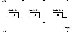
Series connection of two wire switches |
 |
|
This combination is not recommended. Where it seems unavoidable
we recommend the connection of only two switches in series. It should however be
explored whether the desired logic can be realised by an equivalent connection of
switches in parallel eg. A series connection of two Normally Open switches can be
replaced by an equivalent connection of two Normally Closed switches in parallel,
a combination that poses no problems. |
|
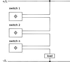
Parallel connection of two
wire switches
|
|
|
|
|
This connection poses no problem barring one limiting factor: the sum of all quiescent
currents flowing through the load may cause a faulty signal where the load is a
PLC. Under ideal conditions, however, upto 10 switches may be connected in parallel.
It is however advised that only one of these switches remain ON at any given moment.
This switch will remove the operating voltage from the other switches connected
in parallel; if a second switch now has a target in front this will result in a
brief load drop-out when the first switch turns OFF (when this happens the supply
voltage becomes available to the second switch which turns ON after a small delay). |
|
|
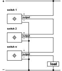
Series connection of three wire switches
Provided the above are considered upto 10 switches can be connected in series. |
|
|
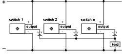
Parallel connection of three wire switches This is as illustrated below. Please note the addition of isolating diodes; not incorporating these diodes will cause the LEDs of all the switches to light up when any one switch is damped. |
|
|
|
|
This connection basically poses no problem. It should however be considered that the quiescent currents of all undamped switches also flowing through the load should not cause a faulty signal say where the load is a PLC. Where this is no problem upto 30 switches can safely be connected in parallel. |