Standard Target - Size
As per the CENELEC standard EN 50010, the rated operating distance of an Inductive
Proximity Switch (IPS) is specified assuming that the target is a square plate,
1mm thick, made of mild steel. The dimensions of the square are indicated below.
|
|
Sensor Diameter
|
Target Size (mm)
|
|
8mm flush or non-flush
|
8 x 8
|
|
12mm flush or non-flush
|
12 x 12
|
|
18mm Non-flush Mounting
|
18 x 18
|
|
18mm non-flush
|
24 x 24
|
|
30mm flush
|
30 x 30
|
|
30mm non-flush
|
45 x 45
|
|
Targets smaller than those specified above would result
in sensing distances that are less than those specified.
|
Non-standard Target
Targets not of mild steel will result in sensing distances that are different from
those specified. The approximate correction factors for various target materials
are indicated below.
|
|
Target Material
|
Correction Factor
(% of rated distance)
|
|
Cast Iron
|
110
|
|
Stainless Steel
|
70
|
|
Brass
|
50
|
|
Aluminium (thickness < 0.05mm)
|
90
|
|
Aluminium
|
40
|
|
Copper
|
40
|
|
As an example consider a switch with a rated operating
distance of 10mm. This distance is specified for a Mild Steel target of dimensions
as mentioned above. For a brass target of the same dimensions, however, the same
switch would function at approx. 5mm.
|
|
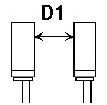
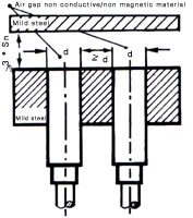
Switch Mounting
Flush Mounting in Metal, as shown in the figure
below, is possible only for those switches whose metal housing extends upto the
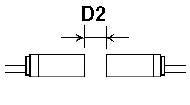
sensing face. Furthermore, to avoid interference, adjacent switches should be mounted
with separating distances, as indicated in the table below.
|
|
|
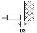
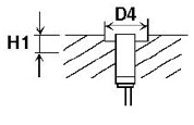
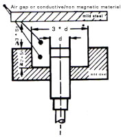
Non-flush Mounting, as shown in the figure below,
is mandatory for those switches whose metal housing does not extend upto the sensing
face. If mounted flush in metal, these switches will not function correctly. To
prevent false actuation from the sides, therefore, these switches must be mounted
in a metal-free zone as shown below. Furthermore, to avoid interference, adjacent
switches should be mounted with separating distances, as indicated in the table
below.
|
|
|
|
|
(mm)
|
M8
|
M12
|
M18
|
M30
|
|
Flush
|
Non-flush
|
Flush
|
Non-flush
|
Flush
|
Non-flush
|
Flush
|
Non-flush
|
|
D1
|
8
|
16
|
12
|
24
|
18
|
36
|
30
|
60
|
|
D2
|
4
|
8
|
8
|
16
|
20
|
32
|
40
|
60
|
|
D3
|
3
|
6
|
6
|
12
|
15
|
24
|
30
|
45
|
|
D4
|
-
|
24
|
-
|
36
|
-
|
54
|
-
|
90
|
|
H1
|
0
|
4
|
0
|
8
|
0
|
16
|
0
|
30
|
|
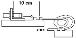
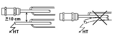
Installation of Switch cable
We recommend routing of the switch cable through a grounded, flexible metal conduit.
No high voltage power cables should be routed through this conduit; cables of other
switches can however, be accommodated within. Furthermore any high voltage power
line should be routed a minimum of 100mm away from the switch cable, as shown in
the figure below. The conduit or cable must be laid and secured in a manner that
no forces are transmitted onto the switch. This is particularly important in applications
where the cable is constantly moved. Note the location of the conduit clamp in the
figure below.
|
|
|
Electrical
Connections
These should be made as indicated below.
Care should be taken not to exceed the voltage limits
specified - generally 10-30V for DC switches and 40-250V for AC switches. For DC
switches, we recommend use of a regulated supply with ripple content less than 10%.
Since AC switches, by themselves, are not protected against short circuits, we recommend
an external series connection, with the load, of a 20 Ohm, 10Watt wirewound resistor
and a 400mA fuse. This combination will provide adequate short circuit protection.
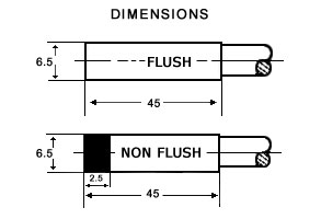
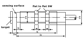
Dimensions
|
|
|
|
|
|
|
|
AVISORS suitable for flush mounting in metal do not have
a projecting front cap. The l3 values, accordingly, apply only to AVISORS,
suitable for Non-flush mounting in metal.
|
|
|
|
BODY
|
NUTS
|
Thread Size d1
(Metric)
|
l2
min.
|
l3
max.
|
l3
max.
|
sw
|
m
|
d3
max.
|
|
|
M 8 x 1*
|
45
|
45
|
13
|
4
|
4
|
15
|
|
M 12 x 1* (Namur)
|
38
|
60
|
8
|
17
|
4
|
20
|
|
M 12 x 1
|
38
|
60
|
8
|
17
|
4
|
20
|
|
M 18 x 1* (Namur)
|
40
|
40
|
9
|
24
|
4
|
28
|
|
M 18 x 1
|
57
|
80
|
9
|
24
|
4
|
28
|
|
M 22 x 1.5
|
57
|
80
|
9
|
24
|
4
|
28
|
|
M 24 x 1.5
|
57
|
80
|
9
|
30
|
5
|
35
|
|
M 30 x 1.5* (Namur)
|
40
|
40
|
16
|
36
|
5
|
42
|
|
M 30 x 1.5
|
57
|
80
|
16
|
36
|
5
|
42
|
|
M 36 x 1.5
|
57
|
80
|
20
|
45
|
6
|
51
|
|
|
|